Vehicle: 2008 BMW E60 535i
Engine: N54 3.0 Liter Turbocharged L6
Symptoms: Extended Cranking Period, Check Engine Light, Reduced Power Mode
Trouble Codes: P0335, DME 2A94, DME 3100
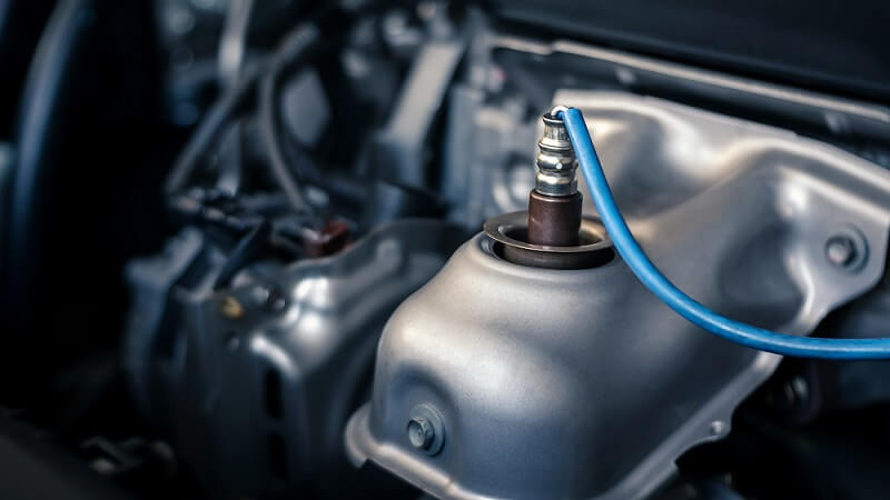
How to diagnose and replace a BMW crankshaft sensor.
A friend brings his car to the workshop the other day and explains that the check engine light is on, along with a reduced power message. When starting the vehicle, the engine would crank for an abnormally long time before it started. A quick scan with an OBD2 Scan tool, revealed code P0335 Crankshaft Position Sensor A Circuit Malfunction.

It’s time for a more detailed scan using a factory-compatible scan tool. In this case, we are using the BMW factory scan tool, ISTA-D. This scan revealed two codes stored in the DME: one relating to the crankshaft sensor signal, and one showing that the turbo boost has been deactivated. The latter is a result of the DME not being able to process the engine RPM via the crank signal. In this case, the DME allows the wastegate to open fully in order not to create and overboost the issue, due to potentially incorrect RPM data.
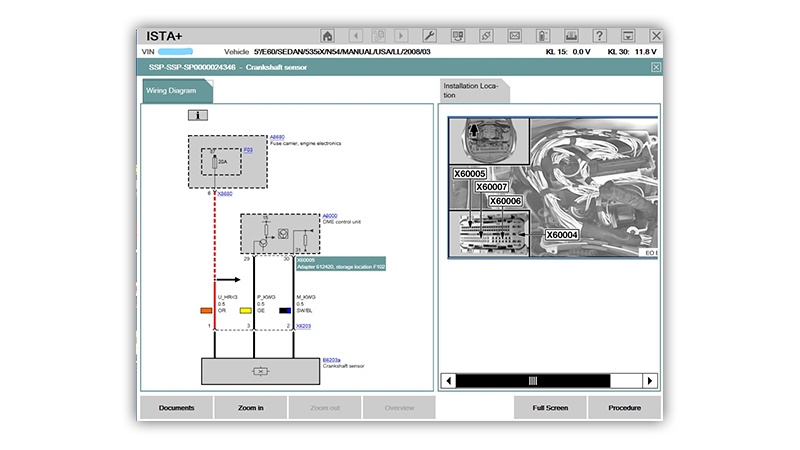
The factory scan tool is equipped with integrated diagnostic and wiring info, which is extremely helpful in diagnosing these systems quickly. A quick look at the wiring diagram and component locations gives us some idea of how to test the system. In this case, it is easier to access the DME for testing than it is to access the crankshaft sensor connector. Testing the signal at the DME is the preferred method anyway because it eliminates any faults in the signal wiring from the sensor to the DME.

In order to access the DME, we will need to remove the cabin filters and the plenum chamber cover. Unclip the metal retainer on both the cabin filters, disconnect the hood switch and the sensor next to it, and lift the cabin filter units out of the plenum. Now is a good time to replace the cabin filters if you haven’t done so recently.
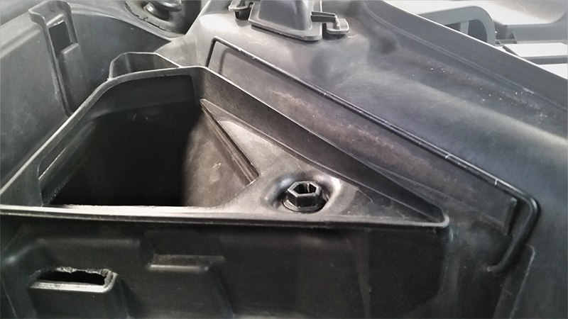
Next, in order to remove the covers, turn the six 13mm plastic clips a quarter turn to the left. Be careful not to turn them too far, or they may break. Then, remove the two T25 Torx screws on either side of the covers. Slide the middle locking retainer towards the driver’s side of the vehicle (LHD), and then remove the two halves of the plenum cover.
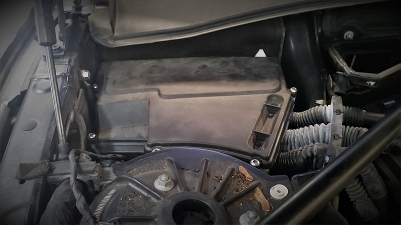
Now we can access the E-box, which contains the DME. Remove the five 5mm hex screws, and slide the locking bar at the rear of the box toward the passenger’s side of the vehicle, and remove the cover.

According to the wiring diagram, the yellow wire (GE) is the signal input from the crankshaft position sensor and is located at pin 29 of connector X60005. We will back probe the wire at the connector to attempt to acquire a signal.
The crankshaft position sensor is a hall-effect sensor, which provides a digital on/off signal, and should produce a square wave signal while the engine is running. The quickest and most precise way to test the signal is with an oscilloscope. If you do not have access to an oscilloscope, you can use a digital multimeter with some degree of certainty. We will cover digital multimeter testing later.
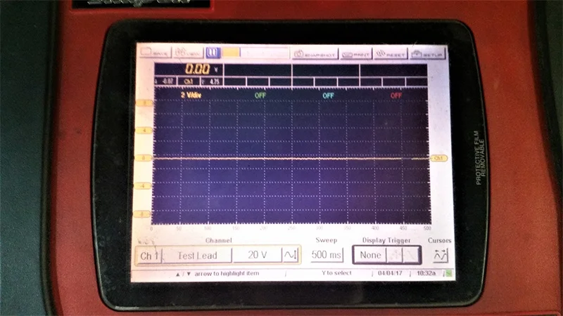
IThe vehicle may need to be taken for a test drive in order to duplicate the symptoms. In this case, it is suspected that the crank signal cuts out wen the engine is at operating temperature. With the engine running, the scope reveals that the signal is stuck at exactly 0 volts, there is no square wave signal as expected. This indicates that the signal is somehow shorted to ground. We will need to access the sensor connector for further testing.

Remove the four T45 Torx bolts connecting the tension strut to the bulkhead and shock towers, and remove the tension strut out of the way for better access to the crankshaft sensor.
The crank sensor is located at the rear of the engine, on the lower left-hand side, just below the starter motor. On the E60 chassis, with the N54 engine, we can access the sensor with relatively minimal disassembly. It’s a tight fit, but the sensor is accessible while working from underneath the hood. The location is the same on the N52 and N55 engines, and depending on the chassis, more or fewer components may need to be removed in order to gain access. For instance, on the N52 engine, you may need to remove the intake manifold in order to get to the sensor.

The connector must be disconnected from the sensor in order to test the voltage. After disconnecting the sensor, remove the protection clip from the connector to expose the wires. Using your digital multimeter set to DC voltage, test the wires according to the wiring diagram, with the ignition in the on position, and the engine off.
- The orange wire (OG) should have battery voltage (approx. 12 volts). This power is supplied via the DME relay through Fuse 03.
- The black/blue wire (SW/BL) should have a good ground (approx. 0.0 volts). This power is supplied via the DME sensor ground circuit.
- The yellow wire (GE) should have a 5-volt reference signal (approx. 4.5-5 volts). This is the signal voltage supplied from the DME, which the crankshaft sensor pulls to the ground to create a square wave signal. If the sensor is connected with the engine running, you should see approx. 2-3 volts if it is operating correctly.
If the voltages are all correct at the crankshaft sensor connector, we can presume that the crankshaft sensor is defective. In this case, based on our oscilloscope pattern, it is internally shorted to the ground.

We will be replacing the sensor with a new VDO crankshaft position sensor. VDO is the OEM supplier for this particular sensor.

To remove the sensor, loosen the E8 external torx bolt using a long extension and a wobble or universal socket. Take care not to allow dirt or debris into the sensor opening. When installing the new sensor, be sure to install a new o-ring. Lubricate the o-ring with silicon grease to ease installation. Start the bolt by hand, taking care not to cross the threads. Take your time here, because the last thing you want to do is turn this job into a rethreading project. Reconnect the connector after reinstalling the protection clip.
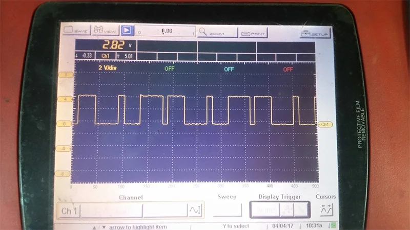
Note that the different length of the spaces in the waveform is how the DME references the position of the crankshaft.
Before reassembling the vehicle, we will test the signal once again to verify the repair. Here, we have a good clean square wave with approximately 0 volts on the bottom and approximately 5 volts on the top, as the teeth on the reluctor wheel pass the sensor.
Now that the engine is cranking normally and producing a good signal, we can reassemble the components in the reverse order that they were removed. Clear any faults in the DME. Note that if you clear the faults via OBD2, the check engine light will extinguish; however, the factory fault codes will remain stored in the DME. You must have a factory compatible scan tool in order to clear the DME-2A94, and DME-3100 codes.
DISCLAIMER
The information provided on this website is for informational purposes only and is subject to change without notice. While Newparts will attempt to update the information it determines to be incorrect, Newparts does not warrant or represent the accuracy of the information found on this website. You shall have the sole responsibility for verifying its accuracy and shall bear the sole responsibility for using such information. Furthermore, if you use the information on this website to repair your vehicle or to replace parts on your vehicle, you represent and warrant that you have the skill and expertise necessary to perform such work. You further agree and acknowledge that Newparts shall not be reasonable or liable for any damage to your vehicle or other property nor shall Newparts be liable to you for any injury or death resulting from your performance of any work on your vehicle.